Simulation of waves by solving the 2D wave equation using finite difference method.
The program provided for download here is a command line application written in C++.
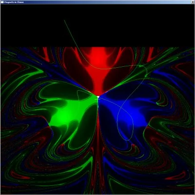
All simulation parameters are read from an INI file which needs to be submitted as the single program parameter. The application opens a single window. Calculation starts immediately. Since waiting for the calculation result is quite boring, I built in some interactivity. So, whenever you move the mouse, a trace starting from the current mouse position is calculated and drawn into the application window. This is a toy, but can be quite useful to get an impression of the final picture by investigating certain starting points and the influence of small variations. If you came to this article looking for the butterfly effect, use this feature and watch the trace morph!
If you want to know what the application is currently calculating, press the right mouse button in order to see the traces for the pixels currently being calculated.
 Image 5: Application window with a calculation in progress.
The application makes use of multicore CPUs by spawning one calculation thread per core and setting the thread affinity to this core.
The configuration file format is the same as for all Windows INI files. You should be familiar with INI file sections, keys, and values.
| Section | Key | Description |
|---|---|---|
| [FIELD] | COLS | Number of columns used for the field discretization. Use this parameter to set the output image width. |
| HEIGHT | Number of rows used for the field discretization. Use this parameter to set the output image height. | |
| SIM_WIDTH (optional) |
Width of the field to be simulated in length units (meter). Set to COLS if unspecified. | |
| SIM_HEIGHT | Length of the field to be simulated in length units (meter). Set to ROWS if unspecified. | |
| WIN_WIDTH (optional) |
Width of the output window in pixels. Use this parameter to adjust the output window width when calculating images larger than the screen. Set to COLS if unspecified. | |
| WIN_HEIGHT (optional) |
Height of the output window in pixel. Use this parameter to adjust the output window width when calculating images larger than the screen. Set to ROWS if unspecified. | |
| [SIMULATION] | THREADS (optional) |
Defines the number of threads spawned for the calculation. If unset, this number equals the number of processors reported by the system. Each thread runs on a different core, resulting in increased performance on multicore systems (ca. 40% on a dual core CPU). |
| FRICTION | Friction coefficient. Friction force is proportional to this value minus velocity of the pendulum. | |
| PEND_HEIGHT | Height of the pendulum plane over the magnet plane in pixels. | |
| DELTA_T | Size of time integration steps in time units. Smaller is more accurate; this is parameter h in the Beeman integration formula. | |
| MIN_STEPS | Number of minimum steps each trace must have before an abort condition is checked. | |
| MAX_STEPS | Number of maximum steps that a trace can have. If this number is reached, the simulation stops even if pendulum did not stop over a magnet. | |
| ABORT_VEL | If pendulum drops below this velocity, it is considered to have stopped. | |
| COLOR_SCHEME | An equation used to determine the color scaling of a pixel. Color scaling depends on the trace length and the maximum trace length. This must be a mathematical expression containing the variables len and max_len (see Image 2). Example: 1/(exp(0.000001*(len*len))) | |
| BATCH_MODE (optional) |
Set this to one for activating the batch mode. In batch mode, the application terminates itself after finishing a calculation. This can be used for creating animations using shell scripting techniques. | |
| [SOURCE ...] |
TYPE | Type of the source. Use either INV_QRT, INV_SQR or LINEAR. Force caused by a source is either proportional to the distance of the pendulum or to the inverse square of the distance. |
| COLOR | Color of the source. | |
| RAD | Source positions are provided in polar coordinates. This is the distance of the source from the simulation center. | |
| THETA | Source positions are provided in polar coordinates. This is the angle of the source from the simulation center. | |
| MULT | Force strength multiplicator. | |
| SIZE | Size of the source. Abort conditions are only checked if the pendulum is closer than that many pixels to a source. |
Examples of configuration files can be found in the data subdirectory. If you want to create your own config files, please start by modifying one of the existing files.