Nuclear chain reactions in gun type atomic bombs - How did the Hiroshima Bomb work?

In this article i will use two real world examples to illustrate how the proper selection of the time step size will influence the result of a numerical simulation. I got the idea for this article after finishing the magnetic pendulum simulation. The problem solved there is chaotic and I wanted to know how reliable the result is and how different it would have looked like had I chosen a different integration scheme. Moreover I wanted to know if it is possible to find points in the simulation where from a set of different integrators every single one converges to a different magnet.
This article will answer both questions. In addition it will shed light on the importance of choosing the right integration scheme and time step size for numerical integrations. Special emphasis will be put on the balance between accuracy and calculation time. For better understanding this article basic knowledge of numerical integration schemes is helpfull. Having heard about Euler, Runge-Kutta and Adams-Bashforth integration schemes is beneficial since i will not explain them in detail here. If you do not know about Runge-Kutta I recommend the article Integration basics by Glenn Fiedler.
The accuracy of an integration scheme is described by the local and the global error. The local error is the error made at a single integration step. The global error is the sum of local errors for many integration steps. Usually the big O notation is used to describe the local and global error of an integration scheme. The maximum global error of an integration scheme of order p (for small step sizes) is a function proportional to h^p or in big O notation: O(h^p). The general rule is: The higher the order p, the better is the integration scheme.
The following single step integration schemes were investigated:
| Method name | Abbreviation | Local error | Global error |
|---|---|---|---|
| Euler | Euler | O(h^2) | O(h) |
| Modified Euler | Euler mod. | O(h^3) | O(h^2) |
| Heun Method | Heun | O(h^3) | O(h^2) |
| Runge-Kutta 3th order | RK3 | O(h^4) | O(h^3) |
| Runge-Kutta 4th order | RK4 | O(h^5) | O(h^4) |
| Runge-Kutta 5th order | RK5 | O(h^6) | O(h^5) |
The following single multi-step integration schemes were investigated:
| Method name | Abbreviation | Local error | Global error |
|---|---|---|---|
| Adams-Bashforth (2 Steps) | ADB2 | O(h^3) | O(h^2) |
| Adams-Bashforth (3 Steps) | ADB3 | O(h^4) | O(h^3) |
| Adams-Bashforth (4 Steps) | ADB4 | O(h^5) | O(h^4) |
| Adams-Bashforth (5 Steps) | ADB5 | O(h^6) | O(h^5) |
| Adams-Bashforth (6 Steps) | ADB6 | O(h^7) | O(h^6) |
The ultimate goal of every simulation is getting accurate results in a reasonable amount of time. You have the choice of the integration scheme. Once you select it, you have to use it with a suitable time step size. The general Problem is, that an accurate high order scheme will require more evaluations thus making it slower. On the other side it will work with larger step sizes thus making it faster. So your choice is either using an accurate scheme with large time steps or a not so accurate scheme with a smaller time step size.
One of the misconceptions is, that if you choose your time step small enough even a bad integration scheme like Euler will produce the corect result. That is incorrect! To find out why lets have a closer look at the global error of a numerical scheme. The following properties of the integration scheme are directly linked to the time step size:
Image 1 is showing the total error as the sum of round off error and global error plotted on a logarithmic scale. As you can see there is a step size for which the total error has a minimum. Every numerical scheme has an optimal time step size for which the total error is minimized. If you select your time step size too small the result will get worse not better!
 Image 1: Total error as the of the sum of round off error and method error.
So far we learned about global error, total error any roundoff error. Now we will compare different integration schemes such as Runge-Kutta or Adams-Bashforth on two sample problems. We will compare the results and draw conclusions about the accuracy of the different integration schemes and their performance.
The first thing you should do with your implementation of an integration scheme is checking it against a known mathematical model for verification. Therefore you need a well known problem with a known analytic solution. I choose the damped harmonic oscillator as the verification model. The behaviour of such a system can be described by the following homogeneous 2nd order differential equation:

 Image 2: Graph of a damped oscillation. (Courtesy of
Wikimedia commons
[1] and
[2])
mit:
The simulation starts with the following initial conditions:
\begin{equation} \nonumber x(0)=x_0 \quad \dot{x}(0)=0 \end{equation}The solution of the differential equation is a function describing the position of the oscilator as a function of time:
\begin{equation} \nonumber x(t) = x_0 e^{-\delta t} (cos(\omega t) + \frac{\delta}{\omega} sin (\omega t)) \end{equation}with:
\begin{equation} \nonumber \delta = {\mu \over {2m} } \quad,\quad \omega_0 = \sqrt {k \over m} \quad,\quad \omega = \sqrt{\omega_0^2 - \delta^2} \label{eq:omega} \end{equation}The difference between analytic solution and simulated solution is the total error. Image 3 shows the total error for all tested integration methods. Almost all of them reproduce the analytic solution well. Only Euler's method, marked by a green "+" symbol, is already failing for the selected time step size.
The relation between time step size and the total error for different integration methods is shown in image 4. The theoretical relationship between the total error and the time step size is confirmed. One can clearly see that there is an optimal time step size for which the total error is minimal. You can also see that the total error is smaller for the high order schemes with RK5 showing the lowest error of all integration methods. Something you will also notice is that the higher the order of the integration scheme the larger is the step size that produces the best result.
If you look at the Euler scheme which marked by the red "+" sign something is noticeable: The minimum of the total error is not even shown in the diagram. In addition it has by far the worst total error, even for small time steps. Any other method could be use with a time step size an order of a magnitude larger and it would still produce more accurate results! Euler's method was discovered by Leonard Euler back in 1768 it's just not what you should use today. The second thing to learn from Image 4 is that overly small step sizes are not just a huge waste of computational time, they actually make the result worse!
Lets have a closer look at the timing of the simulation. After all what one really wants is getting an accurate result without spending too much time. So lets look at image 5 which illustrates the dependency between time step size and calculation time. The basic and obvious rule for all integration schemes is:
The larger the timestep the faster the calculation.
You will see a perfect set of straight lines in a diagram with double logarithmic axis scaling. The relation between time step size and calculation time is not linear. It is a power law. If you cut the time step size in half you double the number of points in the calculation. The bottom line is that you really pay for small timesteps regardless which integration method you use! You'd better choose wisely...
So let's choose wisely and analyze yet another diagram (image 6). This time we see the calculation time vs. the global error squared. This is the point were it's getting interesting because now the relation between accuracy and the calculation time is shown. How long does any of the schemes need to produce a result with a given accuracy? The answer is right here in image 6:
So what do we make of it? A table! At least thats what i make of it. Lets check how long it takes to solve our differential equation and lets say we do not want the square sum of the error to exceed 1e-5. Which scheme does it quickest?
| Rank | Integration Scheme | Calculation time in ms | Time step width |
|---|---|---|---|
| 1 | RK 5 | 0.01 | 0.02 |
| 2 | RK 4 | 0.015 | 0.01 |
| 3 | ADB 5 (* see below) | 0.03 | 0.005 |
| 4 | ADB 4 | 0.039 | 0.0035 |
| 5 | ADB 3 | 0.09 | 0.0015 |
| 6 | Euler mod. Heun | 0.5 | 0.0003 |
| 7 | RK3 ADB2 | 0.7 | 0.0003 |
| 9 | Euler | 36812 | 4e-9 |
Table 2: Integration scheme ranking for an accuracy of 1e-5.
The Winner is the Runge-Kutta 5th order scheme! In this test it performs better than any other scheme because it allows using larger timesteps without loosing too much accuracy. A strong second goes to the RK4 scheme which is still better than the 5th order Adams-Bashforth method. ADB 5 is a bit of a disappointment here because as a multistep method it had all to win this race. The Calculations needed for each timesteps are minimal and yet it came in at the third place. The reason for this result is very simple: The computations needed for calculating the forces for a damped harmonic oszillator are too simple. Multistep schemes can't play out their advantage over the single Step schemes if there is almost nothing to calculate. This results would change when dealing with more complex calculations such as 3-body problems or an N-body problem. So don't write multistep schemes off based on these results!
Another disappointment is the performance of the RK3 scheme which fell behind the modified Euler and Heun methods and came in tied with ADB2. The reason is simple: It needs more calculations but fails to allow much larger timesteps.
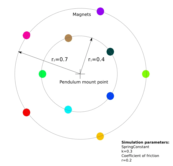
The next test will discuss the accuracy for a magnetic pendulum simulation. The basic principles of the magnetic pendulum are explained in Video 1. The model used in this test is shown in Image 7. The simluation was solved with different integration schemes for a lot of different time step sizes. The results was then compared and analyzed with regard to time step sizes and accuracy.
Video (Englisch): Chaos Theory Explained © 2007 Aldo Cavini Benedetti
Before we start let's have a look at two sample points. The movement of the pendulum is chaotic but chaotic behavior doesnt mean you can't calculate it. It just means that the calculation error increases exponentially with time. So you can't calculate very much into the future because eventually even small variations in the initial conditions will grow and produce results that are totally different.
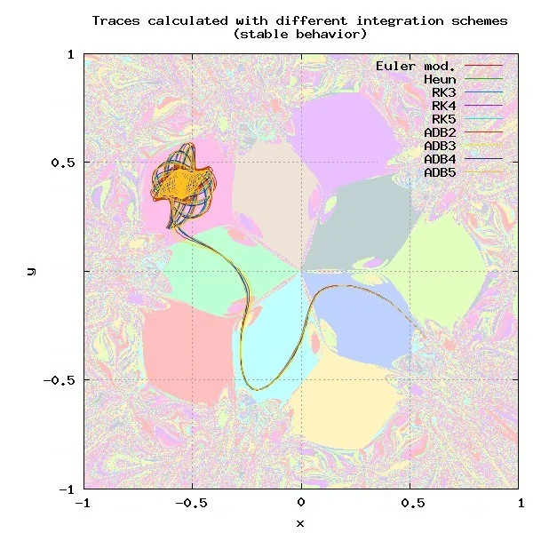
The next test will investigate traces produced by different integration schemes. For this test the initial conditions of all integration schemes were identic so any error in the traces is the direct result of inaccuracies of the integration scheme. As you can see in image 8 There are some points in the simulation domain with virtually no difference between the different results, whilst there are other points were every scheme produces a different result (Image 9).
 Image 7: The second test used a Magnetic pendulum model with 10 Magnets.
 Image 8: There are starting points for which all integration schemes provide almost identic results.
 Image 9: Other starting points yield different results for almost all integration schemes.
With this background it's interesting to see how a complete calculation will look like. First lets start with the resulting image. The following images were calculated with a time step size of h=0.015 s.
 Image 10: Overview of all results obtained with different integration schemes.
Large parts of the simulation domain show a chaotic behaviour, the central part and some structures are reproduceable regardless of the integration scheme. On a first glance all solutions look remarkably similar, but we should have a closer look how similar they are. The left image below is a grayscale image in which the brightness of a pixel is determined by how many integration schemes end up at the same magnet. White means all integration schemes end up at the same magnet, black means none of them have the same final result.
 Image 11: Greyscale image in which the value of a pixel indicates how many different results were obtained. White means all 10
integration schemes produced the same result, black means all produced different results. The result of the RK5 scheme
was used as the reference result.
 Image 12: The resulting image with pixels only shown if 9 out of 10 integration schemes
produced the same result.
It is obvious that there are regions close to the magnets where most or all integration schemes give the same end result. These are regions close to a magnet in which the pendulum doesn't really have much of a choice. If the start point is moved away from the centre (black regions) the results usually differ. Especially paths having many close encounters with Magnets exhibit strong chaotic behaviour. This is due to the force being proportional to the inverse square of the distance to the magnet. Consequently even small differences in the positions will have a dramatic effect on the path taken later on. That is the very nature of chaotic behaviour.
Whatever you simulate in the future keep in mind that even the best integration scheme is always just an approximation of the truth. Using different simulation runs with slightly changed parameters and initial conditions can show you certain trends and provide statistic data on how reliable those trends are. This is usually done with so called Monte Carlo simulations but that is an entirely different topic.
The C++ source code used for creating this article available for download at GitHub. It contains a small framework implementing the different integration schemes in a reusable manner.
For compiling the program you will need the development versions of the OpenGL, SDL, SDL_TTF libraries.